ULTRASONIC JOINT DESIGN GUIDELINES
Perhaps the most critical facet of ultrasonic welding is joint design (the configuration of two mating surfaces). It should be considered when the parts to be welded are still in the design stage, and incorporated into the molded parts. There are a variety of joint designs, each with specific features and advantages. Their selection is determined by such factors as type of plastic, part geometry, weld requirements, machining and molding capabilities, and cosmetic appearance.
BUTT JOINT WITH ENERGY DIRECTOR
The butt joint with energy director is the most common joint design used in ultrasonic welding, and the easiest to mold into a part. The main feature of this joint is a small 90° or 60° triangular shaped ridge molded into one of the mating surfaces. This energy director limits initial contact to a very small area, and focuses the ultrasonic energy at the apex of the triangle. During the welding cycle, the concentrated ultrasonic energy causes the ridge to melt and the plastic to flow throughout the joint area, bonding the parts together.
For easy-to-weld resins (amorphous polymers such as ABS, SAN, acrylic and polystyrene) the size of the energy director is dependent on the area to be joined. Practical considerations suggest a minimum height between .008" and .025" (.2 and .6 mm).
Crystalline polymers, such as nylon, thermoplastic polyesters, acetyl, polyethylene, polypropylene, and polyphenylene sulfide, as well as high melt temperature amorphous resins, such as poly-carbonate and polysulfones are more difficult to weld. For these resins, energy directors with a minimum height between .015" and .020" (.4 and .5 mm) with a 60° included angle are generally recommended.
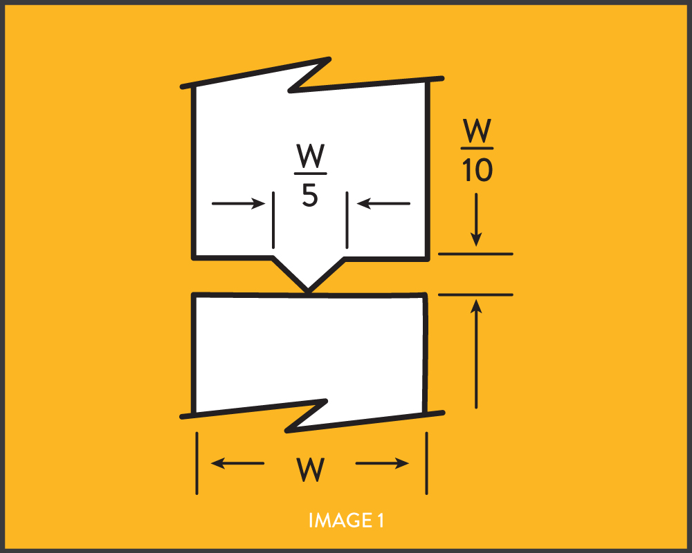
The 90° included angle energy director height should be at least 10% of the joint width, and the width of the energy director should be at least 20% of the joint width. Image 1 (below) shows a butt joint with a 90° included angle energy director. With thick-walled joints, two or more energy directors should be used, and the sum of their heights should equal 10% of the joint width.
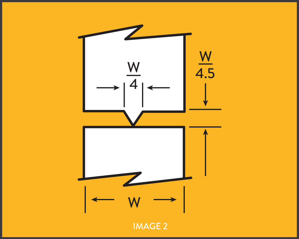
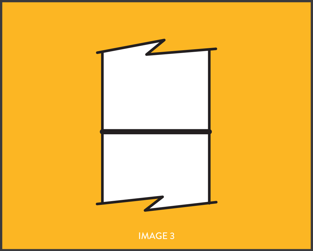
To achieve hermetic seals when welding poly-carbonate components, it is recommended that a 60° included angle energy director should be designed into the part. The energy director width should be 25% to 30% of the wall thickness. Image 2 (below) shows a butt joint with a 60° included angle energy director. Image 3 (below) shows how the ports should be dimensioned to allow for the flow of molten material from the energy director throughout the joint area.
With assemblies whose components are mode of identical thermoplastics, the energy director can be designed into either half of the assembly. However, when designing energy directors into assemblies consisting of a part mode of copolymers or terpolymers, such as ABS, and another part made of a homopolymer such as acrylic, the energy director should always be incorporated into the homopolymer half of the assembly.
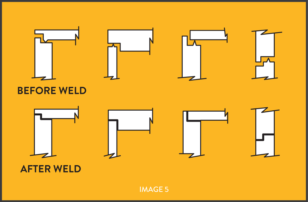
STEP JOINT ENERGY DIRECTOR
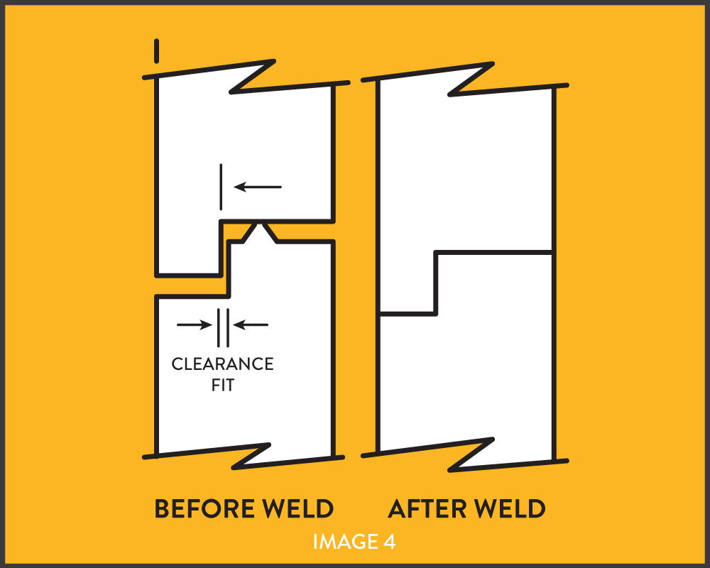
The step joint with energy directory is illustrated in Image 4 (below). This joint molds readily, and provides a strong, well-aligned joint with a minimum of effort. This joint is usually stronger than a butt joint due to the fact that material flows into the vertical clearance. The step joint provides good strength in shear as well as tension, and is often recommended where good cosmetic appearance is required. When working with crystalline materials a 60° included angle energy director should be used instead of the 90° included angle energy director.
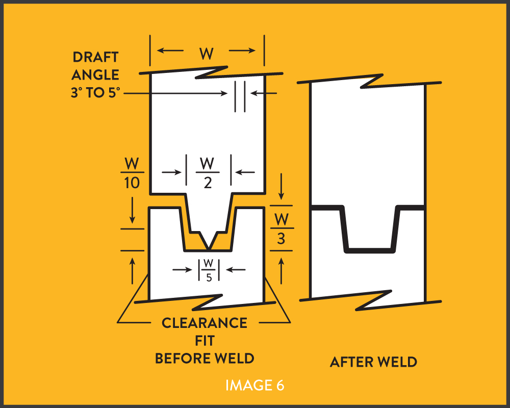
TOUNGUE AND GROOVE JOINT WITH ENERGY DIRECTOR
The tongue and groove joint with energy director is illustrated in Image 6 (below). This joint is used primarily for scan welding, self location of parts, and prevention of flash both internally and externally. It provides the greatest bond strength of the three joints discussed so far.
SHEAR JOINT
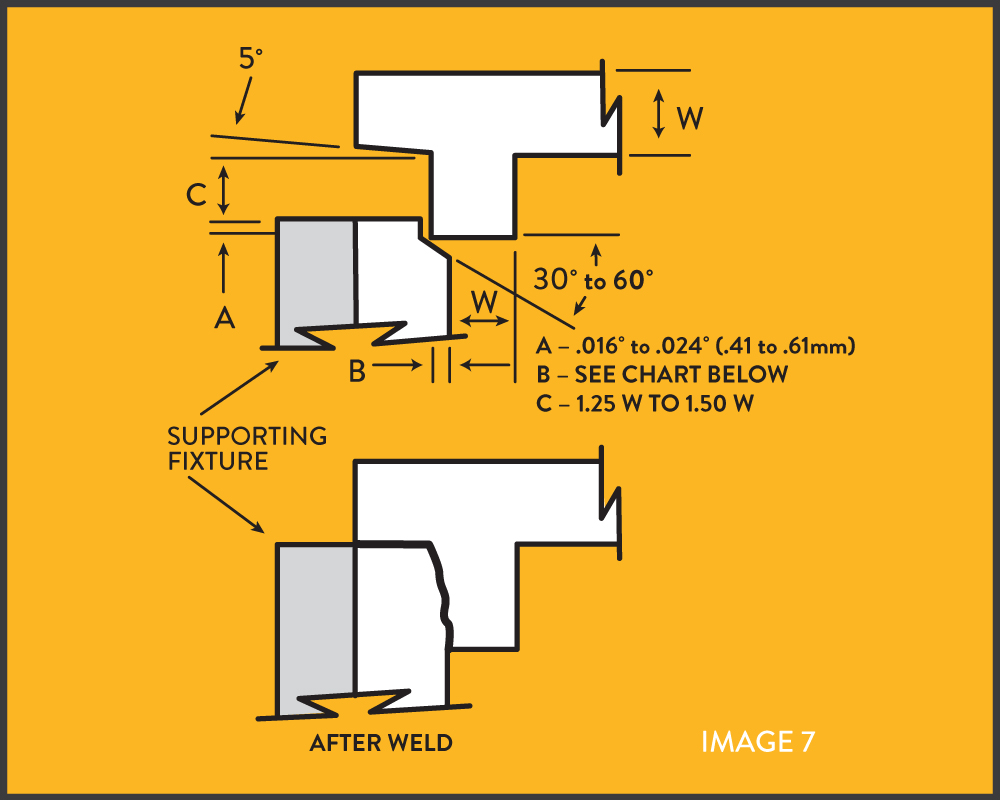
The shear joint of interference joint shown in Image 7 (below) is generally recommended for high-strength hermetic seals of parts with square corners or rectangular designs, especially with crystalline resins.
Initial contact is limited to a small area which is usually a recess or step in either of the parts. The contacting surfaces melt first. As the parts telescope together, they continue to melt along the vertical walls. The smearing action of these two melt surfaces eliminates leaks and voids, making this the best joint for strong hermetic seals.
Initial contact is limited to a small area which is usually a recess or step in either of the parts. The contacting surfaces melt first. As the parts telescope together, they continue to melt along the vertical walls. The smearing action of these two melt surfaces eliminates leaks and voids, making this the best joint for strong hermetic seals.
MAXIMUM PART DIMENSION
Less than 0.75" (19 mm)
.75 to 1.50" (19 to 38 mm)
Greater than 1.50" (38 mm)
INTERFERENCE (B)
0.008" to 0.012" (0.2 to 0.3 mm)
0.012" to 0.016" (0.3 to 0.4 mm)
0.016" to 0.020" (0.4 to 0.5 mm)
The shear joint requires weld times in the range of 3-4 times that of other joint designs because larger amounts of resin are being welded. In addition, a certain amount of flash will be visible on the surface after welding.
SCARF JOINT
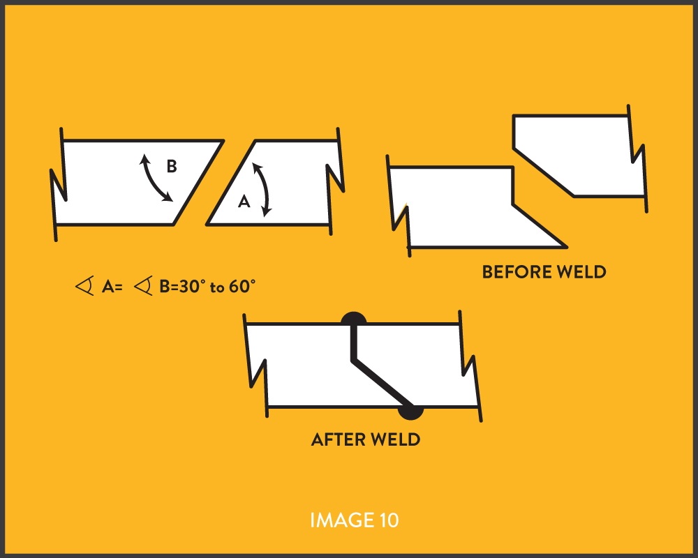
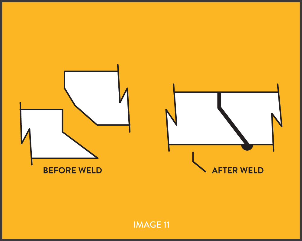
The scarf joint, illustrated in Image 11 (below), is generally recommended to high-strength hermetic seals on parts with circular or oval designs, especially with crystalline resins.
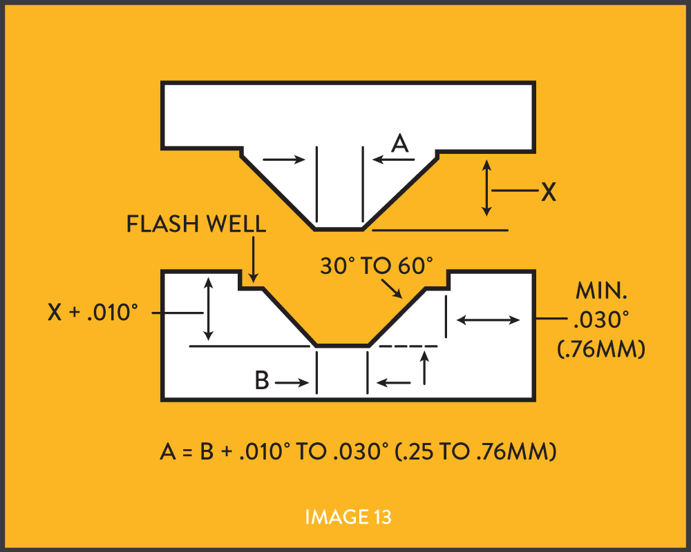
The scarf joint requires that the angles of the two parts be between 30° and 60° and be within one and one half degrees. If the wall thickness is .025" (0.63mm) or less, an angle of 60° should be used. If the wall thickness is .060" (1.52mm) or more, an angle of 30 should be used. Intermediate angles are recommended for wall thickness between .025" and .060" (.063 and 1.52mm).
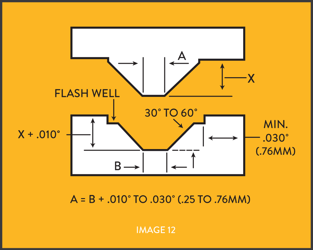
A minimum wall thickness of .030" (0.76mm) at the outer edge of the scarf is recommended to prevent "blowout," or melting clear through the wall, during welding.
The scarf joint is not commonly used due to the difficulties encountered in maintaining component concentricity and dimensional tolerances. However, this joint is highly recommended when limited wall thickness preclude the use of a shear or modified shear joint.
As shown in Image 13 (below), a flash well can be incorporated in the scarf joint to contain the excess molten material generated when the parts are welded. The length of the well should be at least equal to the cross sectional thickness of the part being welded.
Guidelines for the selection and design of heat staking component materials.
Common designs of hermetically sealed joints for circular parts.
Footer
19 Sargent Drive
Bethany, CT 06524 USA
Telephone: 203-393-0639
Toll Free: 866-882-1701
Fax: 203-393-0395
Email: [email protected]